|
General information:
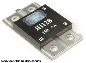
The voltage regulator JA112V is purposed for voltage maintenance of the onboard vehicle network
of the tractor in predetermined limits in all system operation modes of electrical equipment at
change of the rotation frequence of the alternator rotor, electrical load and environment
temperature.
The regulator is produced in a single climatic design О2.1 in accordance with GOST 15150 for
internal market and for export. On extent of protection against penetration of foreign bodies
and water, the item meets design IP68 in accordance with GOST 14254. Against moisture
penetration the regulator is protected by special high-heat-conducting compound with an
operating temperature up to 200 °С. Serviceability and correspondence of item parameters are
saved even at plunging of the regulator to water under condition of protection of demountable
joints. The regulator JA112V is designed on a single-wire power circuit; the item housing is
connected to the vehicle housing. An operating mode of the regulator is S1 in accordance with
GOST 3940.
Applicability: automobiles VAZ-2104, VAZ-2105, VAZ-2107, "Tavria" (till 1991 year of
manufacture) with the alternator G222.
The regulator is mounted in the brush unit of the alternator where the setting of
regulators JA112V or JA112V1 with the help of standard screws is stipulated.
Specifications:
 |
Range of operating temperatures,
°С |
|
-45 .. +100
|
| |
Nominal regulating voltage, V |
14,0
|
| |
Regulating voltage with battery at
t°=(25 ± 2) °С and load of alternator 3А, V |
14,0 ± 0,1
|
| Regulating voltage with battery at
t°=(25 ± 2) °С in range of alternator load from
3A to
Imax*
,
V |
14,0 ± 0,2
|
| |
Maximum current of output circuit,
А |
5,0
|
| |
Thermal compensation of regulating
voltage, mV/°С |
-3,0 ± 1,5
|
| |
- typical, V |
0,75
|
| |
Maximum allowable long-term influence
of increased supply voltage, V |
18,0
|
| |
Maximum allowable influence of increased
supply voltage up to 5 min., V |
25,0
|
| |
Maximum allowable pulse overvoltages
in accordance with GOST 28751, V |
120,0
|
|
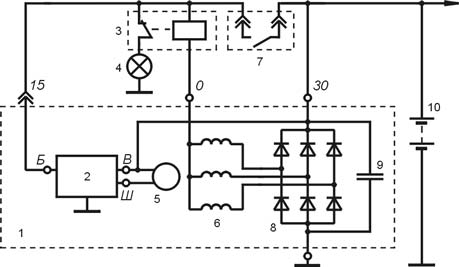
Connection diagram:
1 - alternator;
2 - voltage regulator;
3 - control lamp relay;
4 - control lamp;
5 - field winding; |
6 - stator winding;
7 - ignition lock contacts;
8 - rectifier unit;
9 - capacitor;
10 - battery. |
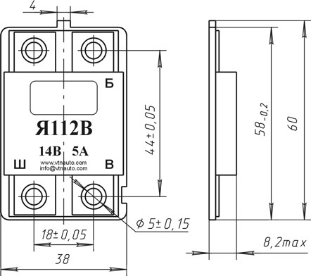
Dimensional drawing (modification of 2002):
|